
FAQ Manual Stage
- Dimensions / tolerances / drawings / Material
- Mounting orientation / load capacity / overhang / moment
- How to read the scale
- Clamp (stopper)
- Operating environment such as temperature / vacuum / vibration
- Maintenance / grease / product life
- Custom order / remodeling / alteration
- Function / How to use
Dimensions / tolerances / drawings / Material
Position of the stage carriage in the drawings (center of the travel range)
As the installation space of the stage is limited, I am concerned about the maximum length of the stage with full stroke.Is the position of the stage carriage in the drawings at the center of the travel range?
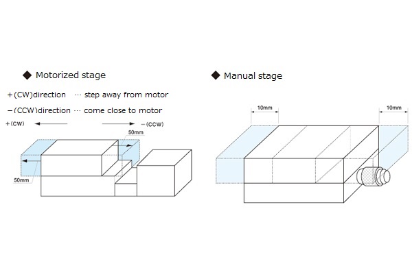
In principle, all the drawings of stages show when carriages are in the center of the travel ranges.
◆ Manual Stage
The travel range is indicated by +/- from the center. For example, in the case of +/-10mm, centering on the position shown in the trace diagram, the stage move 10mm in negative direction and 10mm in positive direction (* full travel length is 20mm)
◆ Motorized Stage
The travel range represents the full travel length. For example, in the case of 100 mm, centering on the position shown in the trace diagram, the stage move 50mm in positive direction (CW) and 50mm in negative direction (CCW)
[exception]
There is an exception in manual Z-axis stages. In that case, rather than showing travel range by +/-, it shows travel range in each of positive and negative directions.
[Tap hole - dimensional tolerance] B11-80 series
What extent the tolerance of the position of the upper surface tap hole of the manual X-axis stage (B11-80 series)?
It is equivalent to general dimension tolerance medium grade .
[Stage height - dimensional tolerance] BDLXR-40 system
Manual X-axis stage what extent is tolerance of (BDLXR-40 ***) of the height?
It is equivalent to general dimension tolerance medium grade.
Can you disclose the parts drawings?
I would like to do a modification in-house, so I would like a parts diagram of the clamp part.
* Other parts are the same answer when it comes to the disclosure of parts drawings.
Parts drawings are not disclosed because they are confidential data.
Stage products with "left-right symmetry" horizontal Z-axis
I am considering to use an L-R (Left-right symmetry) arrangement of manual horizontal cross roller XZ-axis stages. What will be the shape of B63-80AR, symmetric type of B63-80A (L)?
For B63-80AR, only the X axis stage is opposite of B63-80A, and the horizontal Z-axis. X-axis stage is exactly same.
X-axis (lower stage): clamp position is on reverse side, right vs. left (it is the direction which reflected B63-80A of the dimensional drawing on the mirror). Horizontal Z-axis (upper stage): same as B63-80A.
■ Other products with reverse-type products (R type) where the horizontal Z-axis remains same as standard-type products;.
・ Manual horizontal XZ axis: B63 series
・ Manual horizontal thin-type XYZ axis: B72 series
・ Manual horizontal XYZ axis: B76 series
Mounting orientation / load capacity / overhang / moment
Load capacity when mounted with upside down
We are considering using various stages (X axis, horizontal Z axis, tilt, rotation, goniometer) attached to the ceiling. How much does the load capacity deteriorate compared to the load capacity (horizontal placement) described in the catalog?
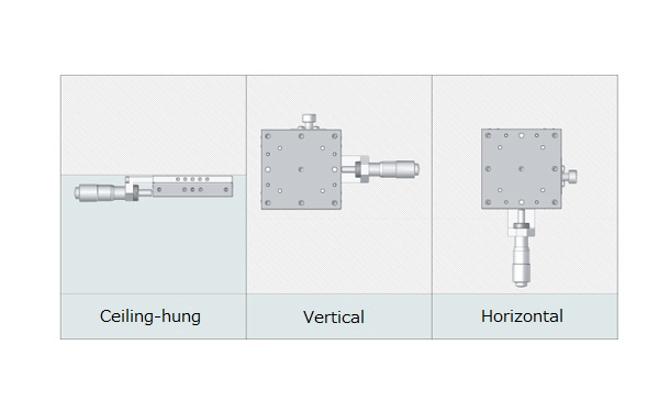
The specifications for each product are based on installation on a flat surface.
As the load applied to the guide of stages changes, it is difficult to clearly define the load capacity of the installation with upside down.
The followings are only for reference.
◆ It is possible to use if the load point is directly below the stage top (center).
* If load is applied to the overhanging position, the load capacity cannot even be estimated, and therefore we do not recommend the use.
#Less than one third of the horizontal load capacity.
・ Various X axis stages
・ Horizontal Z-axis stage・・・B36 series(discontinued products)
・ Rotary stage(fitting type)・・・BRE series
・ Rotary stage(fitting type)・・・B43 series
・ Rotary stage(cross roller guide)・・・B44 / BS43 / B47 series
・ Various gonio stages
◆ Products that can not be used with upside down
・ Z axis stage・・・BSS(BSB)36 / B31 series
・ Horizontal Z-axis stage ・ ・ ・ B33 series(lever type) / B37-60
・ Rotary stage (ball bearing) ・・・ B48 series (discontinued products)
・ Tilt stage (discontinued product)
・ Z axis-mount・・・B34 seires
・ Lab jack・・・B35 series
Load capacity when mounted with upside down
We are considering using various stages (X axis, horizontal Z axis, tilt, rotation, goniometer) attached to the ceiling.How much does the load capacity deteriorate compared to the load capacity (horizontal placement) described in the catalog?
■ In the case of the X-axis stage
If there is a model of Z axis stage with bracket attached to the stage, please refer to the load capacity of that.
model (Example: BSS16-40CZ → BSS36-40CU)
* The load capacity is the weight supported by the micrometer head (feed screw).
■ Other products
The specifications for each product are based on installation on a flat surface. Because the load applied to the stage guide changes, the load capacity of the installation with the side perpendicular cannot be clearly defined.
#The following is only for reference.
◆ It can be used if the load point is near the center of the top of the stage.
* If load is applied to the overhanging position, the standard load capacity can not be estimated, therefore we do not recommend the use.
Less than one third of horizontal placement
・ Horizontal Z-axis stage (lever type) ・ ・ ・ B33 series
・ Horizontal Z-axis stage (wedge) ・ ・ ・ B36 series (discontinued product)
・ Rotary stage (fitting type) ・ ・ ・ B43 series
・ Rotary stage (cross roller bearing) ・ ・ ・ B44 / B47 / BS43 series
・ Various gonio stages
◆ Use in side vertical not recommended
・ B15-150 series
・Horizontal Z-axis stage・・・B38 series(discontinued product)
・ Rotary stage (fitting type) ・ ・ ・ BRE series
・ Rotary stage (ball bearing) ・・・ B48 series (discontinued products)
・ Tilt stage (discontinued product)
・ Z axis-mount・・・B34 seires
・ Lab jack・・・B35 series
Load capacity when mounted on a wall in the direction to move left and right
We are considering using various stages (X axis, horizontal Z axis, tilt, rotation, gonio) attached to the bracket so that the moving direction of the stage is horizontal (side horizontal use).How much does the load capacity deteriorate compared to the load capacity (horizontal placement) described in the catalog?
The specifications for each product are based on installation on a flat surface.
Because the load applied to the stage guide changes, the load capacity of horizontal installation cannot be clearly defined.
#The following is only for reference.
◆ It can be used if the load point is near the center of the top of the stage.
* If load is applied to the overhanging position, the standard load capacity can not be estimated, therefore we do not recommend.
Less than one third of horizontal placement
・X axis stage
・ Horizontal Z-axis stage (lever type) ・ ・ ・ B33 series
・ Horizontal Z-axis stage (wedge) ・ ・ ・ B36 series (discontinued product)
・ Rotary stage (fitting type) ・ ・ ・ B43 series
・ Rotary stage (cross roller bearing) ・ ・ ・ B44 / B47 / BS43 series
・ Various gonio stages
◆ Use in side horizontal not recommended
・Horizontal Z-axis stage・・・B38 series(discontinued product)
・ Rotary stage (fitting type) ・ ・ ・ BRE series
・ Rotary stage (ball bearing) ・・・B48 series (discontinued products)
・ Tilt stage (discontinued product)
・ Z axis-mount・・・B34 seires
・ Lab jack・・・B35 series
Moment rigidity of Dovetail stage
The moment rigidity of Dovetail stage is not on the catalog spec. Why are they not specified?
The dovetail stage has a gap on the sliding surface. There is individual difference in the size of the gap, and the difference in inclination when a moment is given also increases. Therefore, the moment rigidity is not specified.
If there is severe slope due to the moment, please select linear ball guide or cross roller guide products which the moment rigidity value is specified.
I would like to use the rack rail type dovetail stage BDLXR with Z axis
Will there be any problem in using the rack rail type Dovetail stage BDLXR · BDLXB on vertical (Z-Axis) such as in the camera focus.
In the case of a rack rail, there is a possibility that the table may come off because there is no stopper. So, we do not recommend using it on the Z axis.Please consider to take measures such as providing a stopper externally, or to use the B05 / B06 series which has a built-in stopper.
How to read the scale
How do you read Vernier scale?
Please tell me how to read the scale (vernier) attached to the dovetail stages.
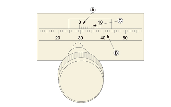
1) Read the 0 position of the vernier of A in 1 mm increments with the B scale. (29 mm in the case of the figure)
2) Look at the scale of A and read the scale C at the same position as the scale of B, and make it a numerical value of 0.1 mm place. (0.6 mm in the case of the figure) 3) The sum of above 1) and 2) shows the current position of the stage. (29.6 mm in the case of the figure)
How to read the scale of micrometer head
Please tell me how to read the scale of micrometer head.
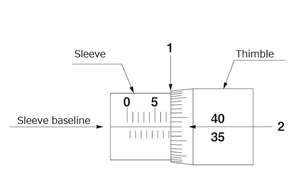
* In the case of reading of micrometer head 0.01 mm
1) Read in 0.5 mm increments how many mm the sleeve position (A) shows at the end of the thimble. (7.5 mm in the case of the figure)
2) Read the value of the thimble at the position where the reference line of the sleeve and the thimble match (B). (0.38 mm in the case of the figure)
3) The sum of above 1 and 2 shows the current position of the stage. (In the case of the figure, 7.5 mm + 0.38 mm = 7.88 mm)
Should the scale of the reverse type rotary stage be read counterclockwise?
The rotary stage has scale by one degree increment. Will the direction of the scale (0 to 360 °) be reversed (counterclockwise) for reverse type products?
The scale (0 to 360 deg) is all clockwise. It is same for both standard (L) and reverse type (R) rotary stages.
Manual horizontal plane Z axis micrometer value
What is the micrometer value at the stroke center of the manual horizontal Z-axis stage (B33 series)?
B33-40A → 3.75 mm
B33-40 KGA → 3.25 mm
B33-60A → 3.75 mm
B33-60 KGA → 6 mm
B33-70 KGA → 6 mm
B33-80A → 5.5mm
* In practical use, mounting dimensional error of about ± 0.5 mm may occur.
Clamp (stopper)
What's the difference between clamps (standard, disk, opposite)?
There are 3 types of clamp methods (standard, disk, opposite). What kind of features do they have?
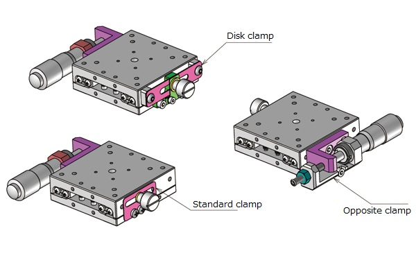
◆ Standard clamp
Tighten the clamp knob, then push and fix the clamp plate on the side of stage by using resin ring.
◆ Disk clamp
Fix the disk attached to the side of the stage by tightening the clamp knob.The load on the stage body can be reduced, and it is possible to suppress the gap when fixed.
◆ Opposite clamp
Press the bolt from the opposite direction of the micrometer. In order to prevent further loosening with a nut, a large fixing force can be obtained.
Countermeasures when the clamp is loosened by vibration
Currently we use standard clamp products (eg BSS16-60C). The vibration of the device loosens the clamp. Can we take any countermeasures?
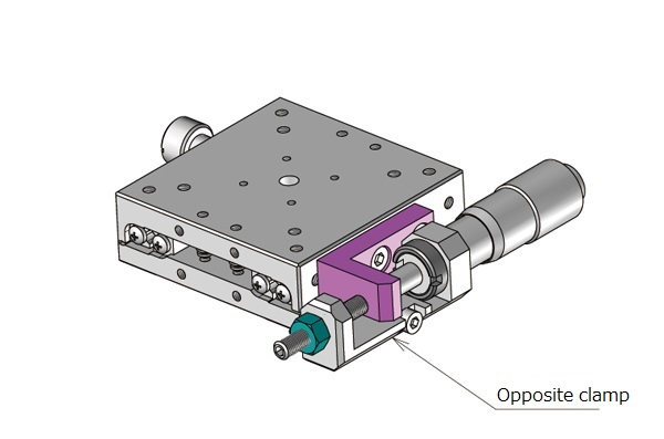
There is a clamp option called "opposite clamp".
It presses the bolt from the opposite direction of the micrometer (or feed screw). Furthermore, a large fixing force can be obtained because the nut is used to prevent loosening.
* The holding power is improved, and the looseness can be reduced.
I want to reduce the gap when tightening the clamp
The stage is used to adjust the initial position of the CCD camera. After adjustment of initial position, it goes out of position when tightening the clamp. Can we take any countermeasures?
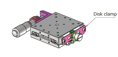
There is a clamp option called "disk clamp".
Fix the disk attached to the side of the stage by tightening the clamp knob. The load on the stage body can be reduced, and it is possible to suppress the gap when fixed.
Manual rotation stage moves after clamped
I use a manual rotation stage. After positioning, it will move even if the clamp on the opposite part of the micrometer is tightened ... Is the usage correct?
Our manual rotary stage is designed to enable fine adjustment after coarse positioning. The coarse clamp must be tightened first. Specifically, the procedure is as follows.
1. Coarse adjustment with the feed knob to the desired position (the knob turns 360 degrees)
2. Tighten and fix the coarse clamp
3. Fine adjustment with a micrometer to the desired position
4. Tighten and fix the micromotion clamp
Operating environment such as temperature / vacuum / vibration
What is the operating temperature range?
Is there a limit to the temperature range in which the stage can be used?
The operating environment of the stage is as follows.
Operating environment: 10 to 50 °C, 20 to 70% RH (non-condensing)
Recommended operating environment: 22 ± 5 °C, 20 to 70% RH (non-condensing)
Is it possible to use in an environment where temperature changes are severe?
Can you use it in the environment with temperature change?
It is possible to use.
However, thermal expansion and contraction occur in the temperature change. It is recommended to use at a constant temperature if it is used for precise measurement. If the temperature change is large, let the stage adapt to that temperature for several hours before using.
* We do not measure data for temperature change.
The use environment of the stage is as follows.
Operating environment: 10 to 50 ° C, 20 to 70% RH (non-condensing)
Recommended operating environment: 22 ± 5 ° C, 20 to 70% RH (non-condensing)
Is there an environment that the stage can not be used?
Is there an environment where you can not use the stage?
Please avoid using in the following places.
・ A place with many dust and powder (especially metal powder)
・ A place exposed to direct sunlight and radiant heat
・ A place near fire
・ A place where corrosive gas or flammable gas is generated
・ A place where water or oil gets caught
・ A place where vibrations and shocks are transmitted
・ A place where there are many solts or organic solvents
Use in a vacuum environment
Use in a vacuum environment
Our standard stages are not designed for vacuum environment.
Grease replacement (Solvay Specialty Polymers Japan Inc., Grease for vacuum, Fomblin YVAC2) is available for limited models (see below).You can order with the option code "-L" at the end of the model number.
■ Grease-replaceable products
・ Support only SS stage (model BSS / BSB)
Operation side clamp & multiple mounting postures are not supported
Use in a clean room
Use in a clean room
Our standard stages are not designed for clean environment.
Grease replacement (only compatible with THK company, clean environment grease, AFF) is available for limited models (see below). You can order by option code (adding "-J" at the end of model number).
■ Grease-replaceable products
・ Support only SS stage (model BSS / BSB)
Operation side clamp & multiple mounting postures are not supported
Countermeasures when the clamp is loosened by vibration
Currently we use standard clamp products (eg BSS16-60C).The vibration of the device loosens the clamp. Can we take any countermeasures?
There is a clamp option called "opposite clamp".
It presses the bolt from the opposite direction of the micrometer (or feed screw). Furthermore, a large fixing force can be obtained because the nut is used to prevent loosening.
* The holding power is improved, and the looseness can be reduced.
* In principle, please avoid the use under environment where vibration or shocks are trasmitted
Use in a humid environment
I want to use the stage at high humidity (70 to 90% etc.) to do environmental test. Is it possible to use it?
When used at high humidity, rust may occur in the guide part of the stage. We do not recommend the use under such environment.
Maintenance / grease / product life
Grease of the guide part of the manual SS stages
Please tell me the grease used in the guide part of the SS stage.
Manufacturer name: THK
Product Name: Grease for clean environment
Model: AFF
* Please note that there is a possibility to change without notice for product improvement.
Grease of the guide part of the manual cross-roller stages
Please tell me the grease used for the guide part of the cross roller stage (linear motion / XY stage).
Manufacturer name: Shell Lubricants Japan
Product Name: Albania Grease
Model: S2
* Please note that there is a possibility to change without notice for product improvement.
Stage product life
Is there a product life on the stage? Please tell me how many years you will lose accuracy.
There is no provision for product life.
Operating environment (temperature, humidity, etc.), load conditions, frequency of use, etc.
It is not possible to estimate the usage period of the guideline because it totally depends on the factors on the user side.
Grease-up frequency
Are there any regulations or recommendations for the frequency of grease up?
There are no regular standards, regardless of the type of grease.
Depending on the driving conditions and guide type, check the grease condition about once a month and apply it as needed.
Grease-up procedure
Please tell me how to grease up.
1) Remove old grease within visible range.
2) Apply with a syringe etc.
3) Make the full stroke operation several times.
4) Wipe out any excess grease.
Custom order / remodeling / alteration
Non-standard correspondence such as special order and remodeling
Is it possible to order some customization such as additional machining of tapped holes in the catalog product?
There are some products that additional work, bracket remodeling, replacement to specified grease, etc. are possible, but others are not.We will answer the possibility after hearing your required specification.
Please contact us with the details of the situation (desired custom specification) from the contact form.
Additional work on stainless steel stage
Is it possible to order additional work on the manual X-axis stage made of stainless steel (BSS16-80C)
Products with stainless steel stages are not available for additional work.
Remodeling of manual stage and installation of motors in-house
We want to change the manual stage into motorized stage by adding motors. Is there any problem with it?
The product is not intended to be modified by the customer.Improper accuracy, product wear, deterioration, etc. may occur.
Adding a connecting block (BDL-40) to Rack Rail Dovetail Stage
We would like to know how to purchase a connecting block (BDL-40) added to Rack Rail Dovetail Stage.
We can take special order in such case. Please contact us from the contact form.
* For your information, we do not sell only the connecting block(BDL-40).
Can we change the position of clamp/micrometer by ourselves?
As for manual stage of the linear ball guide and cross roller, can we change the position of clamps or micrometers and make it left-right symmetry by ourselves?
If the customer changes the clamp to the other side, the top plate and the clamp plate may interfere with each other and may cause scrape.Therefore, we do not recommend to do so.
Function / How to use
Will the stage follow if we turn the micrometer backward?
Will the carriage of the stage follow (return to original point) if we turn the micrometer backward?
Yes, it will follow (return to the original point). The mechanism is to push it back by spring.
Flatness of mounting objects and mounted location
Is there any requirement for flatness of the mounting objects (workpiece) or mounting location?
Mounting an object with a rough surface or attaching it to a surface with a rough surface will deform the stage surface and may affect the accuracy.(The standard of flatness is within 10 μm.) Please confirm the flatness of the monting object and the mounting location.
Z axis stage without bracket
Although we consider using the manual stage in the Z-axis direction (vertical use), the brackets will be made in-house, so it is not required.Is it possible to purchase Z axis stage without bracket?
The configuration of the Z axis stage is "X axis stage + Z axis bracket".Therefore, each stage can be purchased separately as an X-axis stage.
* Example. BSS36-60A → "X-axis stage: BSS16-60AZ" + "Z-axis bracket: ASS60Z-1"
I want to move the manual stage more finely
How can the manual stage operate more finely than a standard micrometer?
For BSS, BSB and B11 series, some models have feed mechanism option of a coarse/fine motion micrometer (minimum reading 0.5 μm) or a fine pitch feed screw (0.25 mm/one knob rotation).
For dovetail stages, there is a type with a coarse and fine movement handle.
* BDLXB ・ B06-11BM ・ B05-11BM etc
Failure diagnosis
Backlash for manual X-Axis stage
The manual X-axis stage (BSS16-40C) is used to adjust the camera position.I'm adjusting it while looking at the image, but I feel that there is a large backlash.
Mounting an object with a rough surface or attaching it to a surface with a rough surface may deform the stage surface and affect the accuracy. (The standard of flatness is within 10μm.) Please check the flatness of the object and the mounting location.
Reverse movement of carriage by turning micrometer
We are using manual X axis stage (BSS16-40C).There was no problem with the direction of moving forward, but it does not return even if we turn the micrometer to the opposite direction.
It has a mechanism to return by coil spring. Please check if the clamp screw is left tightened.
Movement of carriage by turning micrometer after clamping
The carriage make a move by turning micrometer after clamping. Will it be a defective product?
Even if the clamp is tightened, the stage will move if you turn the micrometer.If you want to improve the holding power, we have an opposing clamp option.
However, some products do not have the opposing clamp option. Please check the option code for details on each product page of the catalog.
* BSS/BSB Series (X-axis/XY-axis)
* Some products do not offer the opposing clamp option.
Manual stage does not move even if the micrometer is turned
The manual stage does not move even when the micrometer or feed screw is turned.
Please check if the clamp screw is left tightened.
Terms / definition (accuracy, unit, etc.)
Direction of pitching, yawing, & rolling
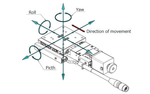
What do "pitching, yawing, rolling (pitch, yaw, roll)" mean?
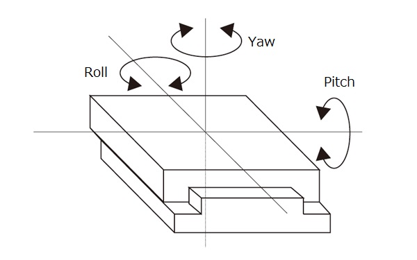
◆ Pitching:
Rotating movement around the axis perpendicular (left and right) to the traveling direction (front and back)
→ Inclination of up and down
◆ Yawing:
Rotating movement around the axis perpendicular (up and down) to the traveling direction (front and back)
→ Inclination of left and right
◆ Rolling:
Rotating movement around the axis of travelling direction (forward and backward)
Difference between straightness, pitching and yawing
Please tell me the difference between straightness, pitching and yawing
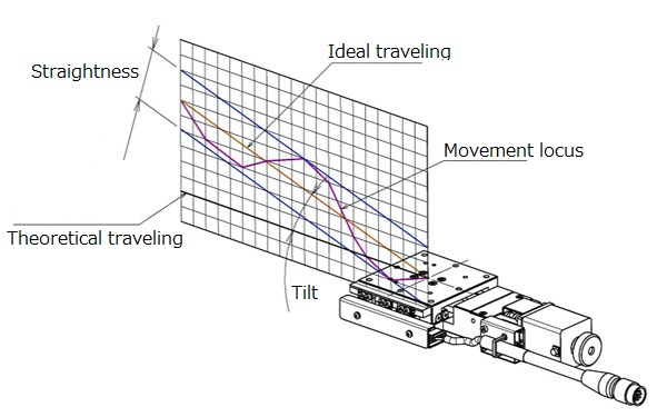
◆ Straightness [unit: μm]
Maximum displacement amount (distance) in the horizontal and vertical directions with respect to the ideal movement axis.
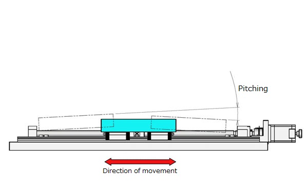
◆ Pitching [unit: "]
Maximum displacement angle in the vertical swing direction .
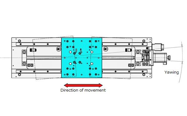
◆ Yawing [unit: "]
Maximum displacement angle in the horizontal swing direction.
Horizontal Z-axis / difference in straightness and verticality of movement
[Horizontal plane Z axis] Please tell me the difference between straightness and verticality of motion
◆ Straightness of movement [unit: μm]
・ Maximum displacement amount (distance) in the horizontal and vertical directions with respect to the ideal movement axis
◆ Verticality of movement [unit: μm]
・ Fix the horizontal plane Z axis stage and right angle reference on reference plane
・ Measure the displacement between the right angle reference and the measuring equipment set on the top of the stage.
・ The maximum difference among the values shall be the "Perpendicularity".
Difference between eccentricity and runout of rotary stage
[Rotary stage]
Please tell me the difference between eccentricity and runout.
◆ Eccentricity [unit: μm]
・ Displacement of center axis of rotation in horizontal direction.
◆ Runout [unit: μm]
・ Maximum difference of displacement with respect to the reference plane when making one rotation with outer circumference as measurement point.
Difference between parallelism and motion parallelism
Please tell me the difference between parallelism and motion parallelism.
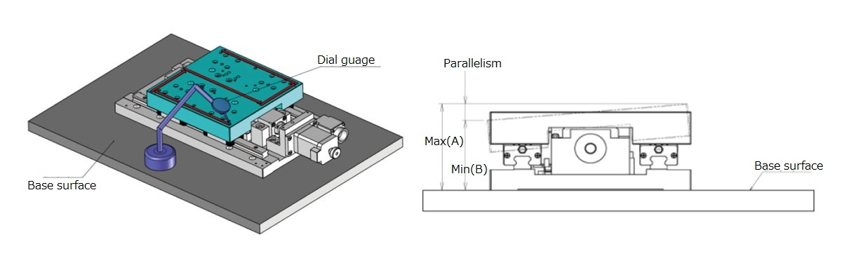
◆ Parallelism [unit: μm]
· Fix the stage on the reference plane.
· A numerical value indicating how parallel the stage carriage and the reference plane are.
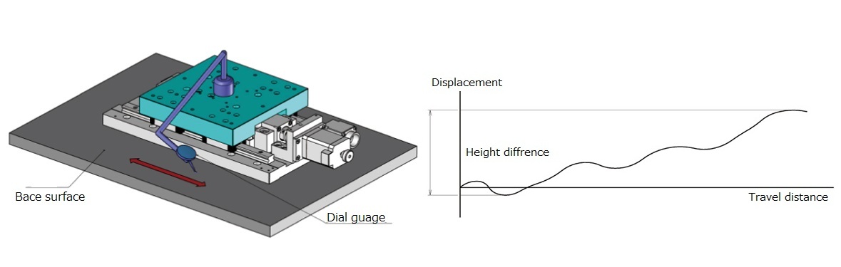
◆ Motion parallelism [unit: μm]
· Fix the stage on the reference plane.
· Place equipment for measuring the height with the reference plane on the stage carriage.
· Maximum difference of measured values by moving the stage
Difference between allowable moment load and moment rigidity
Please tell me the difference between allowable moment load and moment rigidity.
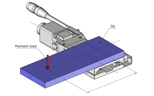
◆ Allowable moment load [unit: N · m] (manual stage)
It is a numerical value that specifies how far the load can be applied away from the stage surface.
* Criteria within tolerance
1. The feeling of operation is not significantly impaired.
2. Accuracy after disconnecting the load can fit within the catalog guaranteed values.
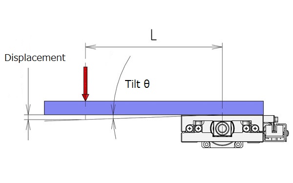
◆ Moment rigidity [Unit: "/ N · cm]
・ The displacement angle per 1 N · cm when moment load is applied toward the stage carriage in the direction of the respective pitch, yaw & roll.
* Based on the distance from the center of the stage carriage (upper surface)
* The moment rigidity value in the catalog is described as a representative actual measurement value.
What is reverse type (R type)
What is the direction of reverse type (R type)?
It is the direction which reflected the manual stage in the mirror.
・In the side push type, the operating position (micrometer / feed screw) and the position of the clamp are switched.
・In the center push type, only the clamp is on the opposite side of the stage carriage.


