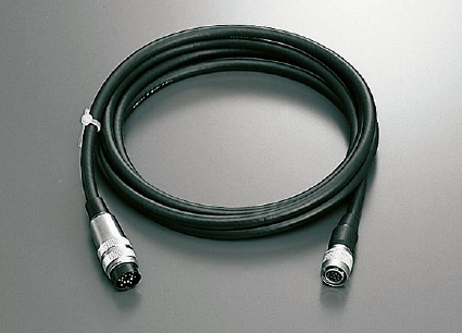
Cable (for motorized stage connection)
Motorized Stage cable
:D214-2-N
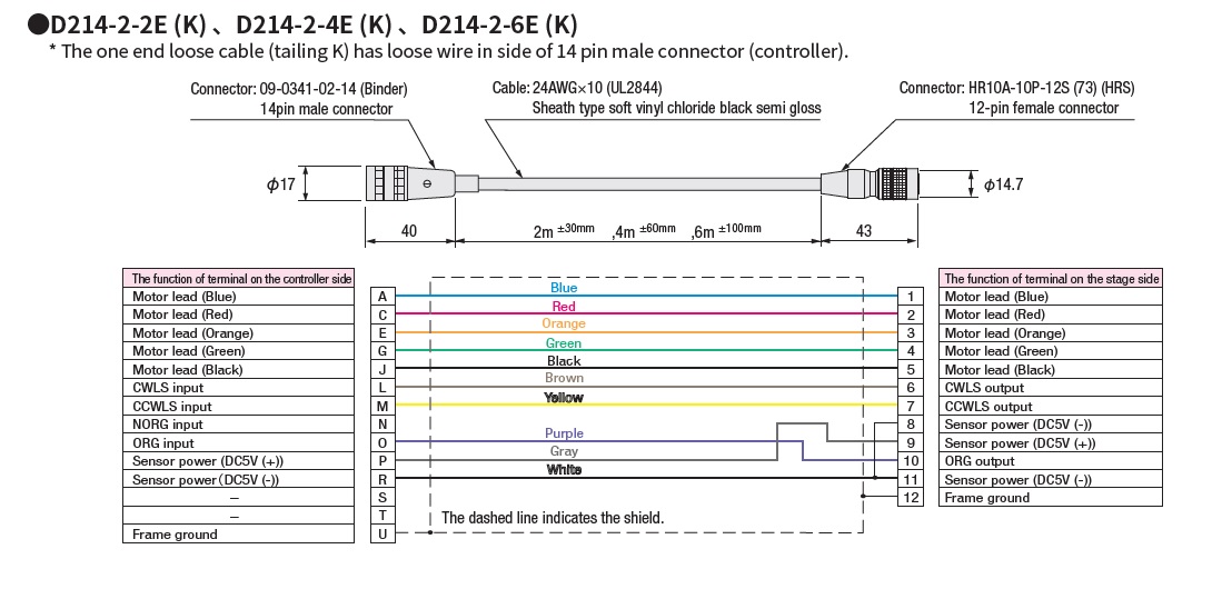
Cable wiring diagram

●When one end is loose, the controller side (left side) of the above cable diagram is a loose wire.

●The sensor power supply voltage is 5 to 24 V specification ±10%.
●The 5V in the wiring diagram above is for use with our controller.

Spec
Cable length[m]2|4|6
Cable type
(For motorized stage)
Standard cable
Stage side connector type12 pin
Option
Relevant product
Spec List
D214-2-2E 2 Standard cable With both end connectors 12 pin HR10A-10P-12S(73)(HRS) 09-0341-02-14(Binder)
D214-2-2EK 2 Standard cable One end loose wire 12 pin HR10A-10P-12S(73)(HRS) Pigtail wire
D214-2-4E 4 Standard cable With both end connectors 12 pin HR10A-10P-12S(73)(HRS) 09-0341-02-14(Binder)
D214-2-4EK 4 Standard cable One end loose wire 12 pin HR10A-10P-12S(73)(HRS) Pigtail wire
D214-2-6E 6 Standard cable With both end connectors 12 pin HR10A-10P-12S(73)(HRS) 09-0341-02-14(Binder)
D214-2-6EK 6 Standard cable One end loose wire 12 pin HR10A-10P-12S(73)(HRS) Pigtail wire